5.3 KiB
\newpage
Introduction
Previously, we designed a digital clock circuit board. Its features included a six digit time display in HH:MM:SS format, oscillator calibration, and internal battery power. Notably, the circuit board had mounting holes to secure it in a final product. The goal of this portion of the project is to design and manufacture the enclosure for this final product.
Design Requirements
- Enclosure geometry
- The enclosure shall have at least two mating pieces
- The enclosure shall meet IP30 specifications
- All parts shall be mechanically held together
- Enclosure safety
- The enclosure shall not have external sharp edges or pinch points
- The enclosure shall not expose any electrical connections
- Enclosure usability
- The digits shall be visible
- The colons between digits shall visible
- Hour and minute increment buttons shall accessible
- Batteries shall be accessible without complete disassembly
- Calibration potentiometer shall not be user accessible
- Manufacturing
- The enclosure shall be FDM 3D-printed.
Results
First, we imported our PCB design into SolidWorks 2025 using Altium MCAD CoDesigner. One of our design goals for the enclosure was to have the seven segment displays flush with the front face. We also decided that rather than standing the clock up, we wanted to lie the clock flat on a table. With this in mind, we decided to build a three-piece enclosure.
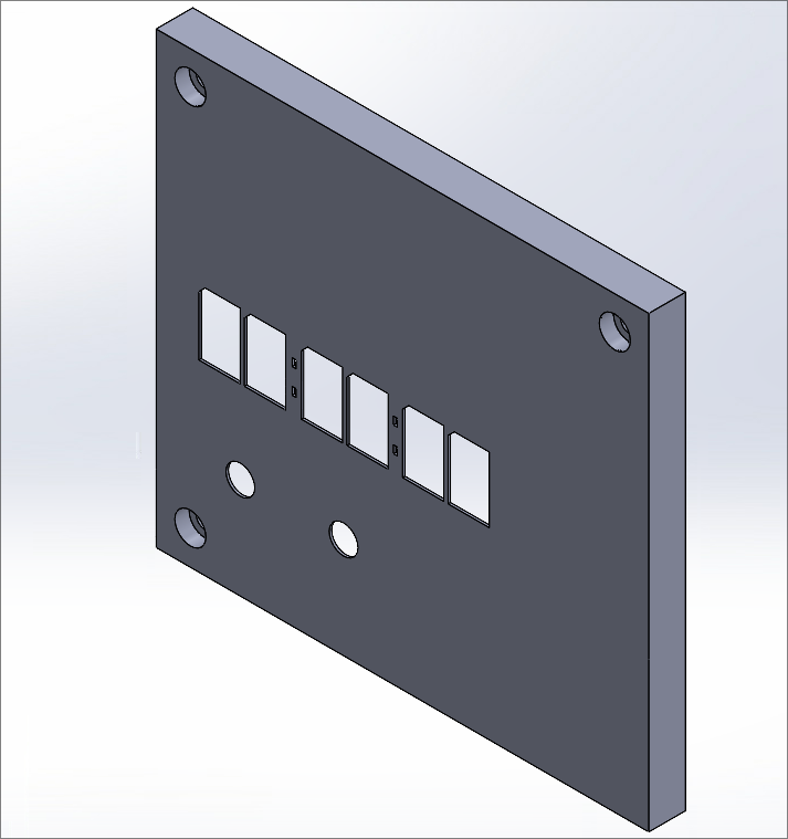
Front Cover
The first piece would cover the front of the PCB and also support it in the three corners with mounting holes. It accepts three M3x10mm screws and keeps the head flush with the top of the enclosure. The front cover also supports the front side of the PCB around its three mounting holes. The walls extend past the ends of the supports to cover the edges of the PCB. We wanted our parts to fit together closely but loosely, since we planned to use fasteners hold the enclosure together. We determined that a 0.5mm gap would allow for this fit [@hubsDesignRules].
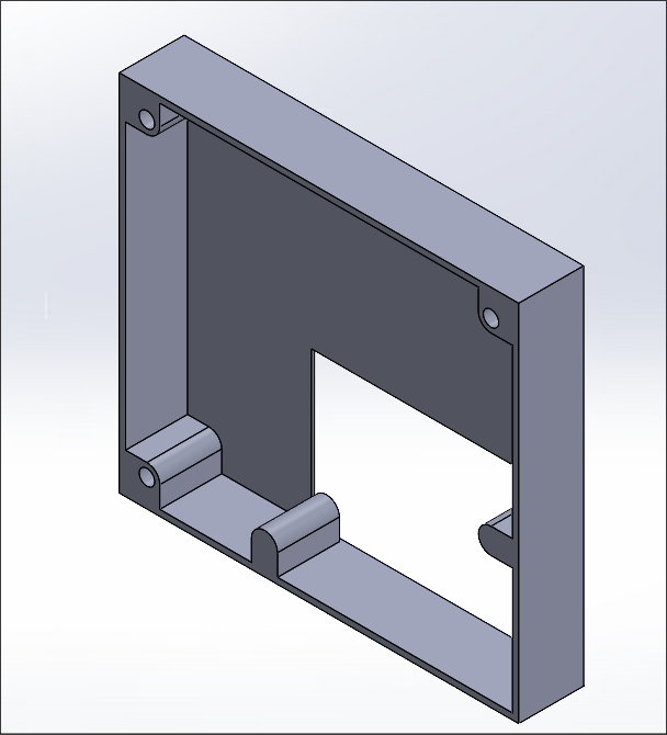
Back Cover
The second piece would support the PCB from the back. Importantly, the supports had to be wide and deep enough to accept M3 heat set inserts, since we planned on screwing the two main pieces of the enclosure together through the PCB mounting holes. The hole dimensions required are a diameter of 4mm and a depth of 6.7mm [@cncKitchen2021]. We forgot to add one millimeter to the depth of the blind hole, so our holes were only 5.7mm deep. Additionally, we also to use this piece to cover the back except for where the batteries are located. This way, the user can access the batteries from the bottom.
Battery Cover
The third piece, the battery cover, is not designed yet. In its current state, we plan to screw the back cover on using M3 screws and heat set inserts. The supports for the heat set inserts are already in place. Unfortunately, there are currently no M3 screws of the required length in stock at the ECE resource room, so we are holding off designing this portion.
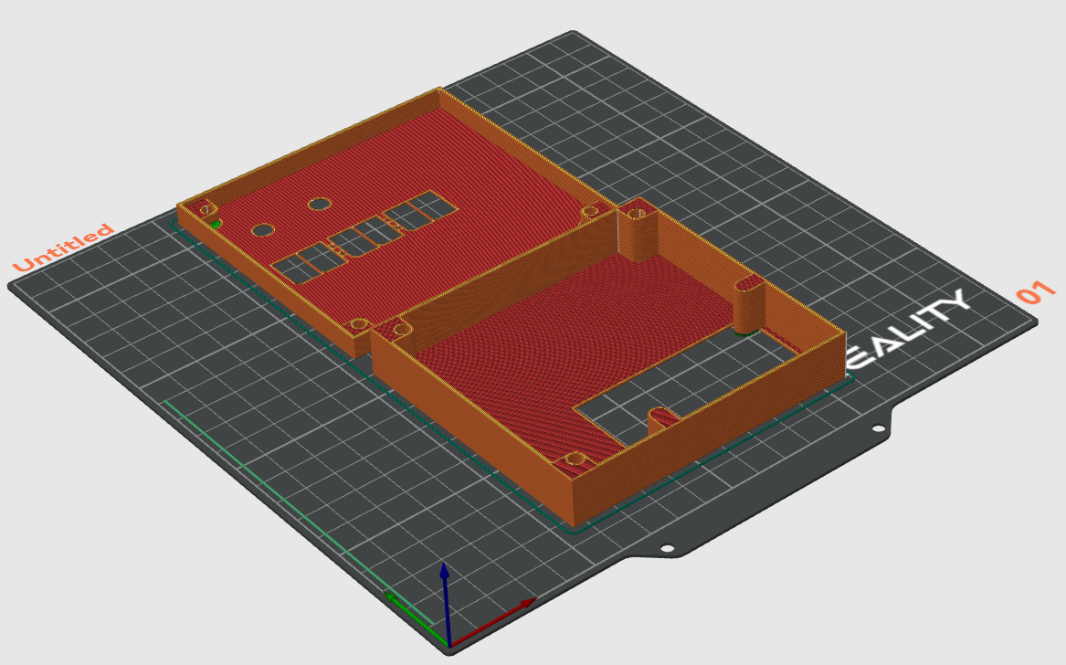
Slicing
With both halves complete in the SolidWorks assembly, we saved each part as an STL mesh to import into OrcaSlicer. The parts were printed on our Creality Ender-3 Pro with a 0.4mm nozzle, 0.2mm layer height, and 15% cross hatch infill. The parts were oriented such that the large covering faces were flat on the baseplate, as this orientation minimized the amount of support material required as seen in figure \ref{fig:slicer}
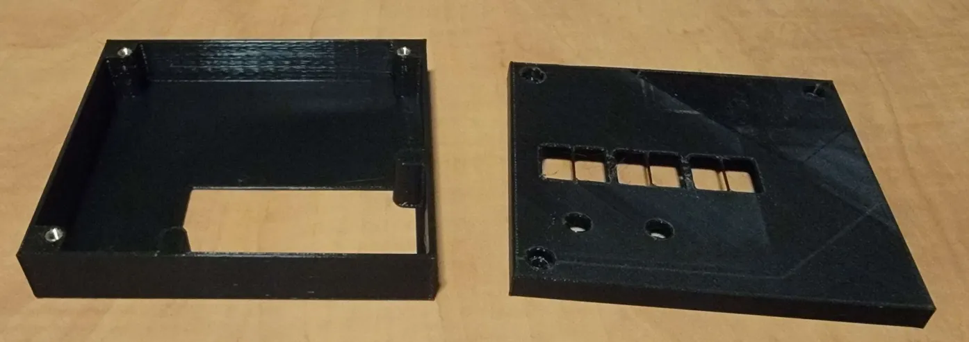
Printing
After levelling the bed, the prints were started on our Ender-3 Pro with black Inland PLA+ filament. The estimated print time was a little over three hours. We ran into some levelling issues, and had to restart the print. Some issues still persisted, but we had confidence that the print would complete successfully, and it did. The only real issue was the less than ideal surface finish on the faces adhered to the print bed. The final parts are seen below:
Reflection
- Measure twice, cut once! Double-check all critical dimensions before printing. In our case, we got lucky that the heat set inserts still went in and the screws did not bottom out.
- Plan ahead! When making the bottom cover for the enclosure, it became apparent that with a simple screw-on battery cover, would need shorter screws than were available in the resource center.
- Use test prints! After printing the bottom cover, we found that there was more support material than expected where the battery cover would go. Unfortunately, since the gap was so small, the support material was very difficult to remove.
- Don't rush! Since we printed on our Ender-3 Pro, we had to manually level the bed. We only had a small time window to level the bed, start the print, and make sure the first layer went down right. We rushed when levelling the bed to get the print started quickly, and our errors left a lot to be desired with the surface finish of the first layer. It might be worth investing in a auto-levelling probe.